Losing grip – Camber gain again
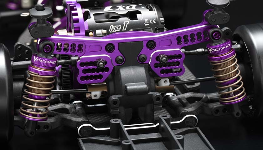
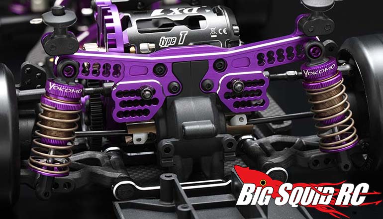
A couple of weeks ago I looked into the geometries behind camber progression – the way camber increases or decreases druing acceleration, depending on the angle of the upper link. Today I will continue on my endeavour to better understand how, or rather why, different settings affect things. One parameter at a time, to keep things simple (for me…). Having looked at upper arm angle, the next obvious step is upper arm length. Pictured above is the rear shock tower of a Yokomo YD-2 SXII – there’s upper link mounting options aplenty. Which to pick, and why?
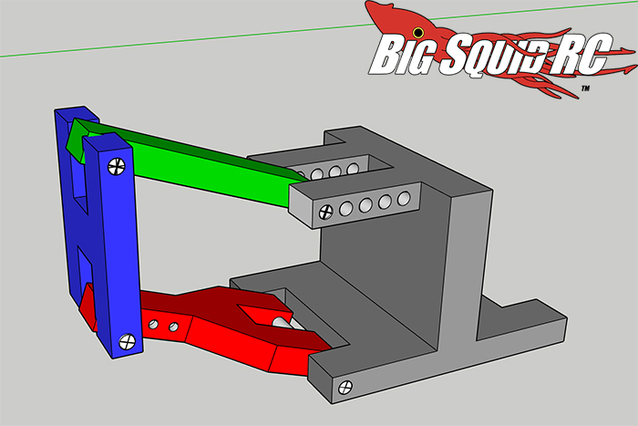
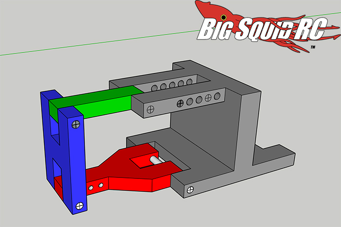
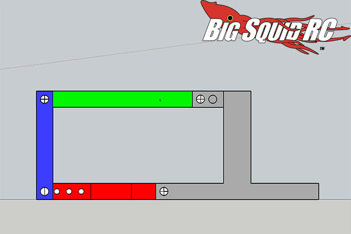
As we have seen earlier, if the upper and lower arm are the same length and parallel, the wheel knuckle will stay at the same angle when the suspension cycles. With the radius (i.e. the length of the link and the A-arm) being the same at both of the knuckle’s attachement points, the upper and lower part of the knuckle both follow identical cirmumferences and the angle between them stays constant. Not perfectly clear? Let’s repeat by having a quick look at some old pictures again. First, the basic setup. Upper link in green, A-arm in red, knuckle in blue, shock tower in grey. Not likely to make it into production, but fit for the purpose of illustration
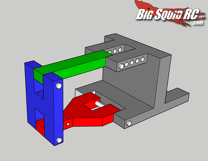
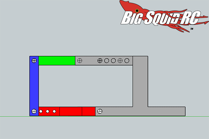
With suspension at neutral, we have zero camber. A-arm and upper link are both the same length, and parallel.
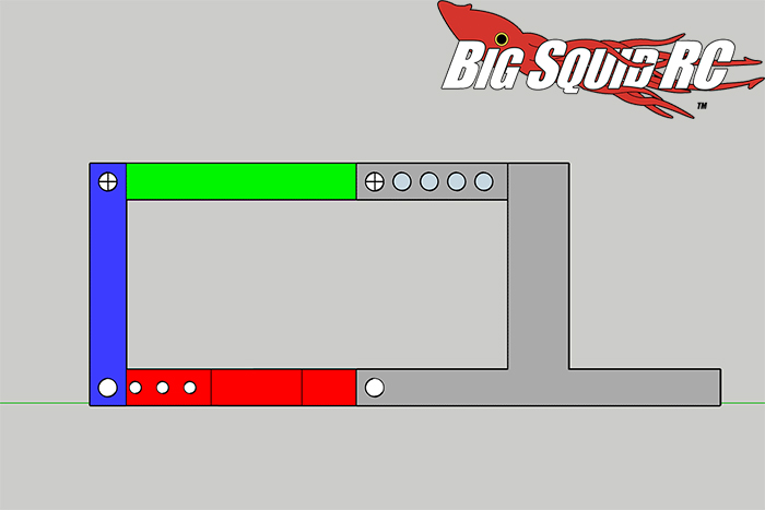
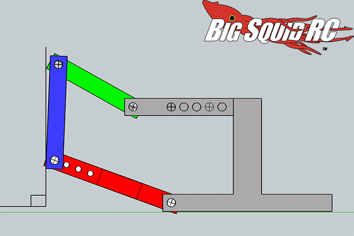
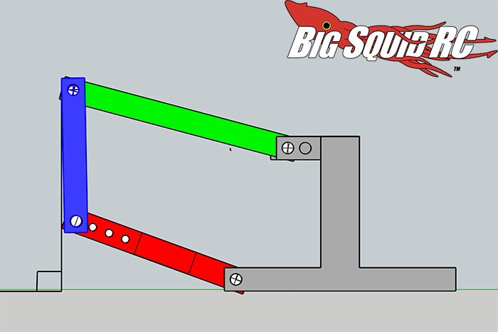
With suspension compressed, we still have zero camber, since the outer part of both A-arm and upper link follow identical and parallel trajectories. Easy.
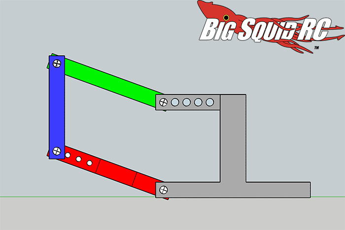
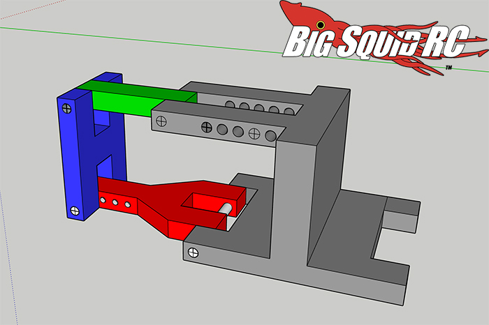
So, what happens if we change the length of the upper link? Let’s shorten it, by moving the inner attachment point outwards. Think of it as the hands of a watch. Before we had two hands of equal length, we now have a long minute hand (the A-arm) and a short hour hand (the upper link). Different lengths, different circumference when they rotate.
In profile, it looks like this:
The upper link will now make a tighter turn, follow a smaller circumference, and it therefore “pulls” the upper part of the hub towards itself as suspension compresses during acceleration. More negative camber, or camber gain if you will. In my rendering, the effect is rather subtle, but clear and true enough.
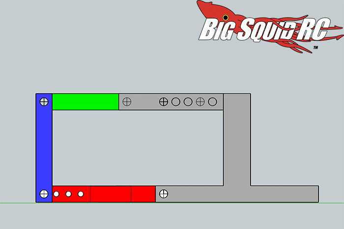
As you would expect, the opposite happens if we increase the length of the upper link, by moving the inner attachement point inwards.
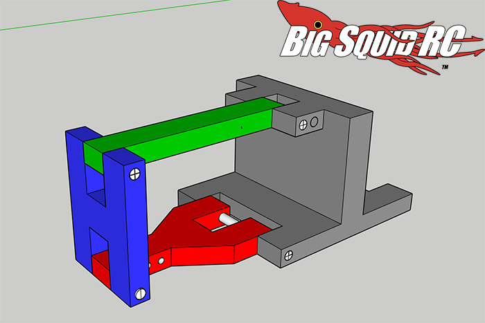
Now the A-arm becomes the hour hand, and the upper link becomes the minute hand. When suspension cycles, the longer one of the two will “push” the knuckle away from itself: less negative camber on compression. From this:
To this:
With neutral camber to start, we actually get positive camber. Less camber gain, for sure. Capisci?
In short, changes of the upper link add up to the following so far, when the car squats. When it rolls, the effects are the opposite, but we’ll look at in another column. That will be more difficult to render, but I’ll try. Anyway, here goes:
More angle (as in leaning more in towards the chassis): increased negative camber – more camber gain.
Less angle: less camber gain
Shorter link: increased negative camber
Longer link: less camber gain
Those statements you can find on a lot of places, my hope is that you now will have a deeper understanding on why it is so. I have known this for a while, but didn’t truly understand it, until I could picture it clearly.
I believe this is where I should finish on some kind of clever note, but, alas, nothing springs into my empty mind. But why don’t you read another column? Or drop me a line and let me know what you’re up to at martin at bigsquidrc dot com.